Duty Point

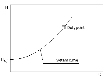
The point is composed of the volume flow Q and the flow rate H.To calculate the design point, the required volume flow (flow rate of the pump) is first determined. Depending on the application, this can depend on various variables (e.g. heat requirement for heating systems, volume of wastewater produced, etc.). The calculated volume flow is then used to determine the frictional losses of the pipeline, which together with the static head then gives the total head of the pump.If a minimum flow velocity is specified for the application and this is not reached for the calculated flow rate, the rated flow rate is adjusted so that the minimum flow velocity is reached. The pump then runs in off mode (intermittent).The duty point of the system is the required operating point for the pump selection. The standard pumps usually have a deviation between the desired duty point and the actual operating point. The permissible deviation depends on the field of application and is partly regulated by applicable standards.With speed-controlled pumps, the speed of the pump is modified so that the set operating point is approached exactly. Especially in systems that are operated in different load conditions (e.g. heating system), this enables efficient operation.Depending on the design of the pump, there are further possibilities for adapting the pump performance curve to the duty point. In addition to changing the speed, the following methods are widely used:
  • Impeller trimming
  • Blade angle adjustment for axial flow pumps
  • Throttling
  • Bypass
 

Shaft Seals

The two most common systems are:The stuffing box – the conventional shaft seal – is, due to its intense maintenance requirements, only rarely used for building services application and then mostly in conjunction with flexibly coupled baseplate pumps. Their use with Inline pumps is restricted to some special design versions.Specific operating conditions require distinctly different types of glanded seals. They are subject to constant observation and maintenance adjustments. Proper lubrication of the gland packing requires a certain leak-age rate which at average working pressures/temperatures and normal water quality amounts to a mean rate of 10 drops per minute. Special manufacturers’ recommendations are to be observed individually. Service life expectancy is between 1 and 2 years, this can sometimes extend to several years on favourable operating conditions. Extremely bad water conditions (sediments, additives, overheating) can however drastically cut short their service life.Glanded seals should preferentially be used in conjunction with shaft sleeves in order to avoid damage to the shaft by aggressive fluids or due to inproper treatment of the glanded packing respectively.The maintenance-free mechanical seal has virtually become standard equipment for glanded pumps in building services and many other applications.They operate without any visible water leakage and do not require any maintenance whatsover during their service life, which runs between 1 and 2 years, maximum 3 years. However, extremely bad water (sedi-ments, use of additives, overheating) can also severely shorten their service life. In such cases it is advis-able to check their suitability or the necessity for special designs with the seal manufacturers.The following mechanical seal configurations have proved to be the most suitable for building services:
  • bi-directional function
  • flexible shaft attachment by means of an elastomeric bellows (automatic compensation of seal seat wear by means of the integrated spring)
  • hard/soft material combination (ceramics or hardened metal to carbon) offering optimum lubricating qualities
  • attachment to a bronze or stainless steel shaft sleeve.
Note: Packed gland and mechanical seals are parts, subject to wear. Dry running is not admissible, as it will lead to the destruction of the seals.

Suction Head With Non-Selfpriming Centrifugal Pumps

That means that the local atmospheric pressure pb is higher than the sum of net positive suction head HH and vapour pressure pv; the inlet pressure is thus no longer required. This interrelation is based on the drastic reduction of the vapour pressure of cold water. In practice, that means:Pumps operating at a negative minimum inlet pressure Hreq are capable of creating a suction lift (not self-priming).The suction capacity is approximately equal to the level of the negative minimum inlet pressure minus 1m safety factor.As pumps normally used in conjunction with building services are generally not of selfpriming characteristics, the following conditions for suction lift operation must be met:
  • Filling and venting of the suction-side pipework including the pump before commissioning.
  • Avoiding air entrainment during pump operation (aeration will result in break-down of suction capability).
  • Avoiding drainage of suction-side piping on standdown of pump by providing and installing a footvalve (danger of leakage due to dirt particles).
Reliance on non-return valves in the discharge pipe is not sufficient, as air can be entrained by way of the shaft seal (mechanical or packed gland seals) on pump standdown.The suction capability of non-selfpriming pumps is, on account of their construction features, generally limited to the range of max. 2 to 4 m. Higher suction lifts (max. 8 to 9 m) and selfpriming operation require the use of Special Pumps.

Positive Displacement Pump

A distinction is made according to the movement type of the displacer. The types are rotary and reciprocating positive displacement pumps.Oscillating positive displacement pumps include
  • Piston pump
  • Diaphragm pump
The following constructions are counted among the rotating positive displacement pumps:
  • Screw pump
  • Progressing cavity pumps (eccentric screw pumps)
  • Rotary lobe pump
  • Gear pump
  • Screw pump
  • Peristaltic pump
In opposition to the centrifugal pumps the positive displacement pumps are suitable for a very high viscosity of the pumped fluid. Furthermore the reciprocating pumps can be suitable for metering and dosing applications.

Glanded Pump

DesignThe uniform feature of glanded pumps is the separation between the pumped fluid and theirst drive motor. The connection between the impeller in the pump body and the motor is made by either a common shaft or by coupled shaft parts. The rotating motor component remains dry (thus the term Dry-Motor Pump). The rotor support by means of roller bearings requires separate lubrication. The pumps are normally driven by IEC-standards electric motors but also by special design motors up to explosion-protected versions.Pump types / function Glanded pumps are of two distinctly different designs:
  • Monobloc Glanded Centrifugal Pumps
  • DIN-Standards Centrifugal End-Suction Pumps
Glanded pumps are louder than glandless pumps. The noise is caused by the roller bearing (ball bearing or needle bearing) and the fan wheel of the surface-cooled electric motor. The noise of the pump itself – flow noise, bearing noise – is completely negligible, unless unusual operating situations occur (cavitation, etc.).

Canned rotor pump

This eliminates the need for shaft sealing by means of a stuffing box or mechanical seal, which is required for other pump types.The pumped medium serves both to lubricate the motor bearings (plain bearings) and to cool the interior of the rotor. This so-called wet space is sealed off from the atmosphere or the motor winding by a can. This can has an average wall thickness of only 0.1 to 0.3 mm and is made of non-magnetic high-alloy steel. The canister is statically sealed using O-ring seals. Function / feature The advantage of this construction is clearly that it is completely maintenance-free. No exchange or messages, no exchange of sealing elements, but perfect function during the entire operating time.The smoothness of this design is remarkable. Apart from the damping properties of the water, in which the rotating parts move, the reason for this smoothness is the sliding bearing of the rotor. This eliminates all rolling or rolling noises that occur in rolling bearings z. B. can occur by means of ball bearings.Not only the smooth running, but also the service life and the degree of susceptibility to failure are decisively influenced by this component.The design of the bearing is one of the most important design features of wet rotor pumps. In addition to the structural design of the bearings, the material pairing of the bearing is of decisive importance for the operational safety of the pump. The following combinations have become established in practice:
  • Ceramic shaft / ceramic bearing
  • Hardened chrome steel shaft / carbon bearing.
The ceramic bearing, shaft and bearing made of the same material, a pairing that contradicts traditional bearing theory, has very little bearing wear on the basis of the extremely hard and brittle material aluminum oxide ceramic with optimal bearing lubrication. However, if there is no requirement for proper lubrication, e.g. B. Dry running due to air accumulation or steam formation in the event of overheating, there is a risk of blockage after a short time. In addition, the ceramic shaft is relatively susceptible to breakage when subjected to mechanical stress, e.g. due to transport vibrations or when attempting to unblock it due to tilting with a screwdriver.In contrast, the two-material bearing – hardened chrome steel shaft / carbon bearing – shows the very good dry-running or emergency running properties of metal-impregnated carbon bearings. In addition, there is the proverbial break resistance of the hardened steel shaft against impacts and vibrations. Operational behavior On the basis of decades of practice with millions of pumps, a statistical mean under normal operating conditions and depending on the pump design has resulted in a service life of approx. 40,000 to 70,000 operating hours. This corresponds to an average of 8-12 years with normal heating operation. The optimal functionality of this construction is also underlined by the fact that quite a few wet-running pumps run for more than 15 to 20 years (over 100,000 operating hours) without malfunction and maintenance.Glandless pumps in building technology consistently have the speed control of the drive motors as a special feature. In the meantime, manually switchable controls are no longer permitted for new installations in many countries and have largely been replaced by automatic controls.

Self-Priming Centrifugal Pumps

The pump suction pipe is then air-evacuated without any special external suction devices.Centrifugal pumps without external or internal suction devices can be operated at a suction lift if the pump body is filled with water before starting the actual fluid displacement. Due to the function of a non-return valve the fluid will be retained within the pump body after switch-off.The construction required for for self-priming capability has a negative effect on the pump efficiency.

Side channel pump

They transport the fluid through a star-shaped wheel into a channel next to the impeller. The delivery heads achieved are 5 to 15 times higher than those of radial impellers.The pumps are self-priming. They are used in particular for the conveyance of liquid-gas mixtures (partial gas conveyance) and for special suction requirements.The efficiency is comparatively low. Therefore, the power range is only up to about 4 kW.Due to the narrow gaps, they are generally not suitable for conveying fluids with abrasive components.