They are used especially in the transport of plastic masses and dispersions.
Like the eccentric screw pumps, they are suitable for the highest viscosities.
In contrast to the piston pump, however, the plunger does not completely fill the cross-section of the displacement chamber. In principle, the piston rod (plunger) is the displacement body here. It therefore does not move along the cylinder wall in a sealed manner. The cylindrical plunger piston is only sealed via a fixed stuffing box.
The inlet and outlet are each controlled by an automatic valve. During the suction stroke, negative pressure is created in the pump chamber. The valve to the suction line opens and liquid is sucked into the pump chamber. During the pressure stroke an overpressure is created in the working chamber, the valve opens to the pressure side and the piston pushes the liquid into the pressure line. In order to compensate for pressure surges, the pressure line in an air vessel contains an air cushion. It is compressed during the pressure stroke and also drives the liquid into the pressure line during the suction stroke due to its stored pressure force. This creates an even flow of liquid.
The standards regulate, for example, the main dimensions of the pump unit. This enables manufacturer-independent interchangeability.
The most important standardization organizations for pumps include:
ANSI American National Standard Institute
API American Pertroleum Institute
BPMA British Pump Manufacturers Association
DIN Deutsches Institut für Normung
HI Hydraulic Institute
ISO International Organisation for Standardization
There are two distinctive designs of glandless pumps, one with dry stator windings (Canned Rotor Motor) and one with wet-stator windings (Wet Stator Motor).
With this design, there is no shaft seal between the pump and the motor. The pumped medium is used for cooling and lubricating the motor at the same time. Glandless pumps are considered to be particularly low-noise, which makes them ideal for use in living spaces. The omission of the shaft seal makes the system particularly low-maintenance and leakage-free. This also makes canned motor pumps interesting in process technology for applications where leakage-free pumping is important.
A disadvantage is the lower efficiency compared to pumps with shaft seals (glanded pumps), especially at higher outputs.
Typical applications for canned rotor pumps are as heating circulating pumps, process pumps for the chemical industry and process engineering and as nuclear reactor pumps. Wet stator pumps are mainly used as submersible pumps in wells and for circulating duties in conventional power plants.
As a displacement element, they have an elastic diaphragm whose axial movement is caused either by a direct drive by means of a drive rod or indirectly by transmitting the displacement pressure of a plunger.
The flow is thus directed from the outlet of the preceding impeller into the inlet of the following one. The high-pressure centrifugal pump is often designed as a ring-section pump.
With the same design, the delivery pressure (delivery head) increases proportionally to the number of impellers for the same flow rate. If the additional losses due to flow diversion in the inlet and outlet are neglected, the hydraulic efficiency is independent of the number of stages. Thus the characteristic curves of multistage centrifugal pumps can be converted as follows as a good approximation:
Hn(Q) = n/m · Hm(Q)
P2,n(Q) = n/m · P2,m(Q)
ηhydr,n(Q) = ηhydr,m(Q)
NPSHn(Q) = NPSHm(Q)
n, m – Number of impellers
Q – Flow
H – Head
P2 – Shaft power
η – efficiency
They are mainly used in installations requiring large flow rates, abnormally high working pressures (cast steel, S.G.iron) or special temperatures or pressures respectively. Their installation requires heavy foundations and extensive piping configurations. The high flow velocities within the pump body and the pump ports often require special noise attenuation measures.
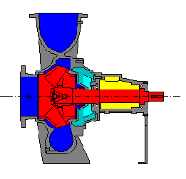
The following diagram depicts a sectional view of a flexibly-coupled end-suctionpump without motor, coupling and baseplate.
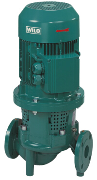
The pumps can be directly pipe mounted or, if necessary, be separately supported by foundations or brackets.
The high continuous temperature rating (up to 140°C) and the vibration-free operation on account of respectively shaped pump housings, impellers and drive motors are the decisive design features of this, especially for building services developed pump design. Low flow velocities through the housing as well at the pump ports make special noise attenuating measures (flexible connections) superfluous.
A centrifugal pump is a hydraulic flow machine in which the transport of the pumped medium is realized by utilizing the centrifugal forces (centrifugal forces) caused by the rotation of the impeller. Energy is transferred by deflecting the flow within the impeller blades.
Centrifugal pumps are typically applied for pulse free, continuous or intermittent operation, but they are not suitable for dosing or metering applications. The strengths of this process are in the continuous, pulsation-free operation. Another advantage is the relatively simple design and good adaptability, which avoids high maintenance costs.
The application is limited with regard to the viscosity of the pumped medium. With increasing fluid viscosity the efficiency is decreasing. Therefore the application is practically limited to fluids with a kinematic viscosity up to 100 .. 150 mm²/s. For higher viscosities positive displacement pumps are preferred.
Important parameters are head, flow rate, power requirement, efficiency and NPSH value. The parameters are generally shown as performance curves depending on the volume flow (flow rate).
We use cookies to ensure that we give you the best experience on our website. If you continue to use this site we will assume that you are happy with it.ACCEPTDENYPrivacy policy