Pump Performance Curve

The graph of the curve is shown dropping from top left to bottom right with increasing rate of flow. The slope of the curve is determined by the pump construction and particularly by the design of the impeller. The characteristics of the pump duty curve is the inter-dependent relationship between capacity and head. Each change of head effects a consequential variation in the rate of flow. High rate of flow -> low head Low rate of flow -> high head Though it is the frictional resistance of the installed pipe system which determines a given pump capacity, the respective pump can take up only one duty point on its curve. This duty point is the intersection of pump H-Q curve with the system H-Q curve. 
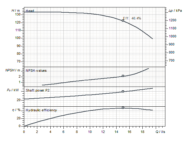
In addition to the Q-H performance curve, the following performance curves are often found for centrifugal pumps:
  • Power
    • Shaft power P2(Q)
    • Electrical power consumption P1(Q)
  • Efficiency
    • Hydraulic efficiency ηhydr(Q)
    • Total efficiency ηtot(Q)
  • NPSH required NPSHreq(Q)
  • Speed n(Q)
 

Suction Head With Non-Selfpriming Centrifugal Pumps

That means that the local atmospheric pressure pb is higher than the sum of net positive suction head HH and vapour pressure pv; the inlet pressure is thus no longer required. This interrelation is based on the drastic reduction of the vapour pressure of cold water. In practice, that means: Pumps operating at a negative minimum inlet pressure Hreq are capable of creating a suction lift (not self-priming). The suction capacity is approximately equal to the level of the negative minimum inlet pressure minus 1m safety factor. As pumps normally used in conjunction with building services are generally not of selfpriming characteristics, the following conditions for suction lift operation must be met:
  • Filling and venting of the suction-side pipework including the pump before commissioning.
  • Avoiding air entrainment during pump operation (aeration will result in break-down of suction capability).
  • Avoiding drainage of suction-side piping on standdown of pump by providing and installing a footvalve (danger of leakage due to dirt particles).
Reliance on non-return valves in the discharge pipe is not sufficient, as air can be entrained by way of the shaft seal (mechanical or packed gland seals) on pump standdown. The suction capability of non-selfpriming pumps is, on account of their construction features, generally limited to the range of max. 2 to 4 m. Higher suction lifts (max. 8 to 9 m) and selfpriming operation require the use of Special Pumps.

Avoiding Cavitation

  • Increasing the available static pressure at the pump location (positioning the pump at a lower level, e.g. from a roof plant room into the basement to benefit from the increased static head from the higher water column. The pump performance remains unchanged).
  • Lowering the fluid temperature (reducing the vapour pressure pD).
  • Changing the pump characteristics (reducing the driven speed and/or different pump design with a lesser Pump NPSHrequired).
 

Net positive suction head (NPSHr)

Generally recognizable is the strong dependence on the pump speed. If the construction is unchanged: High speed -> High holding pressure head Low speed -> Low holding pressure head In order to take account of any uncertainties in the design of the duty point, these values must be increased by a safety margin of 0.5 m when selecting the pump. By definition a minimum cavitation is permissible at NPSH, whereby the following conditions are allowed:
  • The head of the pump at the nominal point is reduced by 3%.
  • No material damage impairing the function and service life occurs.
Due to the permissible cavitation, cavitation noises can still occur, some of which are perceived as disturbing. In order to eliminate the residual cavitation, it is necessary to provide the calculated minimum inlet head with a surcharge of approx. + 1 to + 5 m. The minimum inlet head must be calculated with a surcharge of approx. This surcharge depends on the speed and the operating point of the pump.