The following applies approximately:
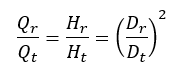
Q = flow rate
H = delivery head
D = impeller diameter
r = index for the reduced impeller diameter
t = index for the reference wheel diameter
The throttle curve H (Q) can be roughly determined from this relationship.
A more precise calculation, however, requires the consideration of performance charts in which an impeller diameter is assigned to each performance curve. The new performance curve is determined by interpolating the conversion from the neighboring curves. In order to fully utilize the efficiency of the method, it is recommended to record an duty chart with at least three performance curves. If there is a large difference between the smallest and largest impeller diameter, some (2..4) intermediate curves are required.
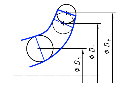
An alternative calculation method is described in ISO 9906. Knowledge of the mean impeller diameter at the leading edge D
1 is required here. According to the standard, this procedure is valid for
-
- Diameter reduction up to max. 5%
- Type number K ≤ 1.5
- Unchanged blade geometry (outlet angle, tapering, etc.) after cutting
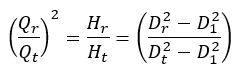
D
1 = Mean diameter at the impeller leading edge
For pumps with a type number K ≤ 1.0 and a maximum impeller diameter reduction of 3%, the efficiency can be considered as unaltered.