Pump Performance Curve

The graph of the curve is shown dropping from top left to bottom right with increasing rate of flow. The slope of the curve is determined by the pump construction and particularly by the design of the impeller. The characteristics of the pump duty curve is the inter-dependent relationship between capacity and head. Each change of head effects a consequential variation in the rate of flow. High rate of flow -> low head Low rate of flow -> high head Though it is the frictional resistance of the installed pipe system which determines a given pump capacity, the respective pump can take up only one duty point on its curve. This duty point is the intersection of pump H-Q curve with the system H-Q curve. 
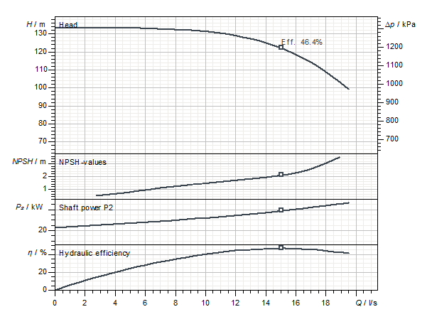
In addition to the Q-H performance curve, the following performance curves are often found for centrifugal pumps:
  • Power
    • Shaft power P2(Q)
    • Electrical power consumption P1(Q)
  • Efficiency
    • Hydraulic efficiency ηhydr(Q)
    • Total efficiency ηtot(Q)
  • NPSH required NPSHreq(Q)
  • Speed n(Q)
 

Shaft Power

The required shaft power of the pump is given as a performance curve depending on the flow rate. The performance curve changes when the speed of the pump changes in accordance with the affinity laws. The shaft power of the pump is directly proportional to the density of the pumped medium. In the case of highly viscous media, the shaft power also depends on the viscosity. Depending on the application and size of the pump, the drive is designed so that the motor power is either greater than or equal to the viscosity of the pumped medium.
  •  the shaft power at the operating point or
  •  the maximum power of the characteristic curve,
in each case plus a security surcharge of at least 5%. The required safety margin depends on the required engine power. While the safety margin is reduced to up to 5% for larger motors, surcharges of over 20% are applied for smaller power values. In addition, the nominal motor power for standard motors must be converted to the ambient conditions. P2 is used as the symbol for the shaft power.  

Required Pump Shaft Power

The shaft power requirement or the power input of the pump are, as the hydraulic performance, also shown in a graph.
  • It demonstrates the dependence of power input on the flow rate.
  • Max. shaft power requirements are reached at max. flow for many pump types.
The drive motor is to be sized to suit that point of the pump. Small pumps (e.g. heating circulators) are typically equipped with motors that allow operation over the entire characteristic curve. This reduces the number of types, and as a result, easier stocking of spare parts is guaranteed. For larger pumps, several motor options are usually offered so that the appropriate drive can be selected according to the operating conditions. If the specified duty point of a pump is located on the left hand portion of the duty curve with a corresponding lower power input it is feasible to select a smaller size motor. In such case however exists the hazard of overloading that size motor if the actual duty point allows a higher flow rate than that calculated (a more flat system curve). As in practice there is always the danger of the duty point having shifted it must be recommended to select the motor to drive a pump with power reserve of approx. 5 to 20% above that theoretically required. To determine the operating costs of a pump it must be principally distinguished between the required shaft power P2 [kW] of the pump and the electrical power input of the motor P1 [kW]. The latter is the basis for determining the operating costs. It can, In case that only the shaft power requirements P2 are given, be determined by dividing that value by the motor efficiency. The electric power input P1 is stated where pump and drive motor are an integrated unit such as submersible pumps. Here it is even customary to state both P1 and P2 values. The required shaft power P2 is generally given in the case of aggregates, where pump and motor are coupled or rigidly connected to non-submersible pumps. This is necessary to allow the use of most distinctly different types of motors – beginning from IEC-standards up to the special design motors – with their varying electrical criteria such as power inputs and efficiencies.