
- Increasing the available static pressure at the pump location (positioning the pump at a lower level, e.g. from a roof plant room into the basement to benefit from the increased static head from the higher water column. The pump performance remains unchanged).
- Lowering the fluid temperature (reducing the vapour pressure pD).
- Changing the pump characteristics (reducing the driven speed and/or different pump design with a lesser Pump NPSHrequired).
Author: bs
Pump
In a narrower sense, in contrast to blowers and compressors for gases and compressible media, pumps for incompressible media are referred to as liquid pumps. This means that the volume of the fluid remains approximately constant as the pressure increases. In practice, this also includes liquid mixtures with a low solid or gas content.
Depending on the direction of the energy flow, pumps belong to the working machines.
Number of Pole Pairs
| Pole pair numbers | 1 | 2 | 3 | 4 | 5 | 6 |
| Synchronous speed (at 50 Hz) n [rpm] | 3000 | 1500 | 1000 | 750 | 600 | 500 |
| Synchronous speed (at 60 Hz) n [rpm] | 3600 | 1800 | 1200 | 900 | 720 | 600 |
Total Head
Defined as the effective mechanical force exerted by the pump onto the pumped fluid and expressed as unit of weight at the local gravitational constant.
It is, at constant speed and constant flow, independent of the density of the fluid, but dependent on its viscosity.
Non-Newtonian Fluids
This is thus indicated that there is no line coherence between deformation and shear tensors and that the viscosity rate is time-related.
Non-Newtonian flow characteristics can be observed with the following fluids:
- gaseous soot in oil varnish
- cereal corn suspensions in water
- waste water sludgesewage
- toothpaste
- mortar
- soap solutions
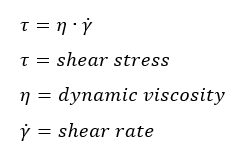
Newtonian Fluid
It is, on one-dimensional flow:, physically defined as:
 Of Newtonian fluid characteristics are e.g. the following:
 Of Newtonian fluid characteristics are e.g. the following:
- water
- oils
- gases
- mercury
- alcohol
- petrol
Rated Pressure
It is stated without a unit quantity. Its numerical value states the permissible working gauge pressure in bar at a temperature of 20°C (68°F) to which a component or specified material may be subjected. In the field of pump technology, it is common to use pressure ratings according to DIN 2401 for the range from PN 1.6 to PN 200.
Preferential designation for pressure ratings are 1.6; 2.5; 4; 6; 10; 16; 25; 40….
Flow velocity
v = Q / A
v – Average flow velocity
Q – Flow rate
A – Area flowed through
For a circular cross section, the following results are obtained with
A = p / 4 – D2
v = 4 – Q / (p – D2)
D – Diameter of the circular area flowed through (internal pipe diameter)
c or v are usually used as symbols for the average flow velocity. Often v is used for the local velocity, while c is used as a symbol for the mean velocity. The DIN 24260 provides the symbol v for the average speed.
The average flow velocity is an important parameter when selecting the optimum pipe diameter for a new pipeline.
Minimum flow
For special applications, the minimum flow rate is also specified in technical standards and regulations via the minimum flow velocity.
Required Pump Shaft Power
The shaft power requirement or the power input of the pump are, as the hydraulic performance, also shown in a graph.
- It demonstrates the dependence of power input on the flow rate.
- Max. shaft power requirements are reached at max. flow for many pump types.