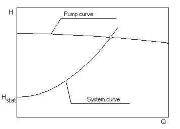
The system performance curve is composed of a static and a dynamic component.
Hsystem = Hstat + Hloss(Q)
The static component Hstat is independent of the flow velocity (and thus of the flow rate). It contains the geodetic height difference as well as the pressure difference between suction and pressure vessel or inlet and outlet point of the system under consideration. In closed circuits (e.g. heating circulation) the static heed is always zero.
The dynamic part of the performance curve describes the piping losses, which depend on the flow rate. In the case of turbulent flow of NEWTON liquids with constant loss coefficients of the system components, the characteristic curve results in a square parabola. If the static head and the duty point are known, the system curve can be shown with sufficient accuracy.
“It indicates the values of Flow and Head which will be obtained at stationary operation with the respective speed-related pump H-Q curve.”
The specified duty point is defined to be that point on the system H-Q curve for which a pump is to be selected in line with the calculated hydraulic design criteria. The objective of the selection is (apart from other criteria, such as maximum efficiency) to minimise the deviation between the specified and the actual duty points.
The actual duty point is always located at the intersection of pump H-Q curve and the actual system H-Q curve. At constant speed it moves up the pump H-Q curve with increasing friction losses towards a lower flow rate. The duty point should be chosen as close as possible to the point of optimum efficiency.

The head for the duty point of the pump is composed of
- the static head (static = independent of the flow rate)
- height difference between suction side and discharge side liquid level (geodetic head)
- pressure difference between discharge side and suction side tank (for closed tanks)
- the required outlet pressure, if any
- the friction loss head from the pressure losses in the piping system as a function of the flow rate
The useable mechanical work transferred from the pump to the fluid being pumped, related to the weight force, is called head H of the pump. At constant speed n and constant flow Q, it is independent of the density of the pumped liquid, but dependent on its viscosity.
It can be calculated by the pressure difference divided by the density of the pumped fluid and the local gravitational constant.
For Newtonian fluids one can consider the head independent from the pumped fluid for kinematic viscosities less than 20 mm²/s. By this reason it is especially suitable to present the characteristic curve of centrifugal pumps.
For pumping water the value is equal to the pressure given in meters of water column.
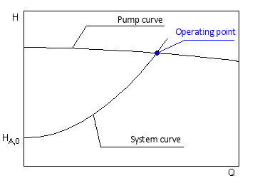
It indicates the values of Flow Q and Head H which will be obtained at stationary operation with the respective speed-related pump H-Q curve.
The specified duty point is defined to be that point on the system H-Q curve for which a pump is to be selected in line with the calculated hydraulic design criteria. The objective of the selection is (apart from other criteria, such as maximum efficiency) to minimise the deviation between the specified duty point and the actual operating point.
The operating point is always located at the intersection of pump H-Q curve and the actual system H-Q curve. At constant speed it moves up the pump H-Q curve with increasing friction losses towards a lower flow rate. The duty point should be chosen as close as possible to the best efficiency point.
