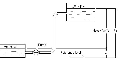
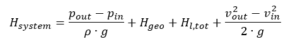
The required pumping head in a branchless pipeline is determined from BERNOULLI’s equation for one-dimensional, stationary flow of incompressible fluids:pin, pout = pressures on suction respectively discharge liquid levels
ρ = fluid density
g = gravity (9.81 m/s2)
Hgeo = static height difference between suction and discharge liquid levels
Hl,tot = total pipe friction loss between inlet and outlet areas
vin, vout = mean flow velocities at inlet and outlet liquid level areasThe mean flow velocities at the inlet and outlet areas are, based on the Continuity Law, mostly insignificantly small and can be neglected, if the tank areas being relatively large compared to those of the pipe work. In this case, above formula will be simplified to:The static portion of the system H-Q curve, that part that is unrelated to the rate of flow, reads:For closed circulating systems this value becomes zero.The total friction losses are the sum of the frictional losses of all components in the suction and delivery piping. They vary, at sufficiently large REYNOLDS numbers, as the square of the flow rate.g = gravity (9.81 m/s2)
Hl,tot = total friction loss between inlet and outlet areas
vi = mean flow velocities trough pipe cross-section area
Ai = characteristic pipe cross-sectional area
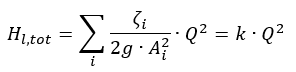
ζi = friction loss coefficient for pipes, fittings, etc.
Q = flow rate
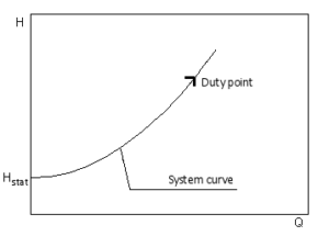
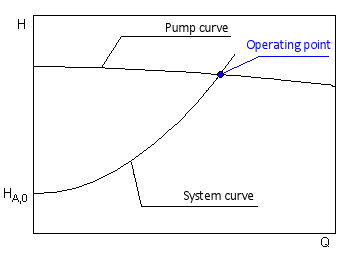
k = proportionality factorUnder the above stated premises the parabolic system H-Q curve can now be drawn:The proportionality factor k is determined of the specified duty point. The intersection of the system H-Q and the pump H-Q curves defines the actual operating point.
The system performance curve is composed of a static and a dynamic component.Hsystem = Hstat + Hloss(Q)The static component Hstat is independent of the flow velocity (and thus of the flow rate). It contains the geodetic height difference as well as the pressure difference between suction and pressure vessel or inlet and outlet point of the system under consideration. In closed circuits (e.g. heating circulation) the static heed is always zero.The dynamic part of the performance curve describes the piping losses, which depend on the flow rate. In the case of turbulent flow of NEWTON liquids with constant loss coefficients of the system components, the characteristic curve results in a square parabola. If the static head and the duty point are known, the system curve can be shown with sufficient accuracy.
This means that the local air pressure p<sub>b</sub> is higher than the product of the holding pressure head HH and the vapour pressure and makes a supply pressure at these temperatures unnecessary. This correlation is causally related to the drastic decrease in vapour pressure at cold water. In practice this means:Pumps with negative minimum head H<sub>req</sub> are able to operate in suction mode (not self-priming).The size of the suction capacity corresponds approximately to the value of the negative minimum suction head minus 1m safety range.Since the pumps normally used in building services engineering do not normally self-priming, the following conditions must be met to ensure suction operation:
Filling and venting of the suction-side pipeline including the pump before commissioning.
Prevention of air intake during pump operation (in case of air pockets, collapse of the suction function).
Prevention of the suction line running empty when the pump is at a standstill by using a foot valve (danger of leakage in case of contamination).
Non-return valves in the discharge line are not sufficient, as air can be sucked in via the shaft seal (mechanical seal or stuffing box) when the pump is at a standstill.In general, the suction capacity of normally priming pumps is limited to a range of max. 2 to 4 m due to their design. For higher suction heights max. 8 to 9 m and for self-priming special pumps must be used.
It is highly recommended to always select the smaller pump if the specified system duty point is between two possible pump curves. The resulting capacity reduction has, in heating systems, no appreciable effect on the effective heating performance. The positive effects are lower noise levels, lower investment costs and improved economy. For heating installations it is customary to undersize pump capacities up to 10% below the specified duty.To avoid Cavitation (vapour formation within the pump) it is necessary to maintain at the pump suction port an adequately high positive pressure (static head) in relation to the vapour pressure of the fluid being handled. The minimum required inlet heads for Glandless pumps are generally listed in pressure charts. Glanded pumps require calculations in accordance with the NPSH information.
NPSHavailable = NPSH of system
pe = Pressure available system inlet liquid level
pb = Barometric pressure
pD = Vapour pressure of pumped fluid at the pump suction inlet
ρ = Density of the pumped fluid at the pump suction inlet
g = Local gravitational acceleration (9.81 m/s2)
ze = Static level difference between system inlet liquid level and a reference level, the negative sign becoming applicable if the reference level is above the system inlet liquid. The reference point is the centre of the impeller.
Hv = Friction loss in suction-side system.The reference point for the NPSH value is the centre of the impeller, i.e. the intersection of the pump shaft axis with the plane perpendicular to it through the outer points of the blade leading edge.The duty point of a centrifugal pump can only be a permanent duty point if complying with:NPSHavailable > NPSHrequired + safety margin.
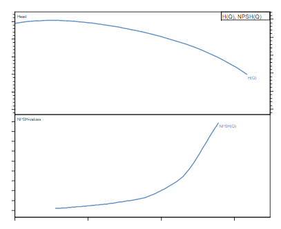
The NPSHrequired is the lowest NPSH value at which definite cavitation criteria (i.e. wear due to cavitation, vapour formation, vibration, noise, head loss) can be contained.As a function of the volume flow Q, NPSHreq is a characteristic of the centrifugal pump and is specified for many types as pump characteristic curve NPSH(Q). At low volume flow rates, the NPSH value is almost constant, whereas it rises steeply at high volume flows.The NPSH value of the pump changes with the speed as well as the impeller diameter.For some pump types, the NPSH value can optionally be reduced by an additional construction. A typical example of this is the inducer, in which an axial impeller with a small number of blades is arranged directly in front of the actual impeller of the centrifugal pump.
It is calculated from the absolute energy level minus the evaporation pressure level. The evaporating head shall be calculated with the evaporating pressure corresponding to the temperature prevailing in the inlet cross-section of the pump.The NPSHavailable value is the system-specific NPSH relating to the given flow rate and the fluid characteristics.The NPSHrequired is the lowest NPSH value at which definite cavitation criteria (i.e. wear due to cavitation, vapour formation, vibration, noise, head loss) can be contained.
The top four criteria are:
WHAT for a medium? –> Pumping medium
HOW MUCH Amount? –> Flow rate
WHERE, how far, how high? –> Pipe geometry
WHICH pump unit should be used? –> Delivery unitIf the flow rate and pipe geometry are known, the head can be calculated with the help of the pressure loss calculation. Flow rate and head together form the duty point for the pump design.
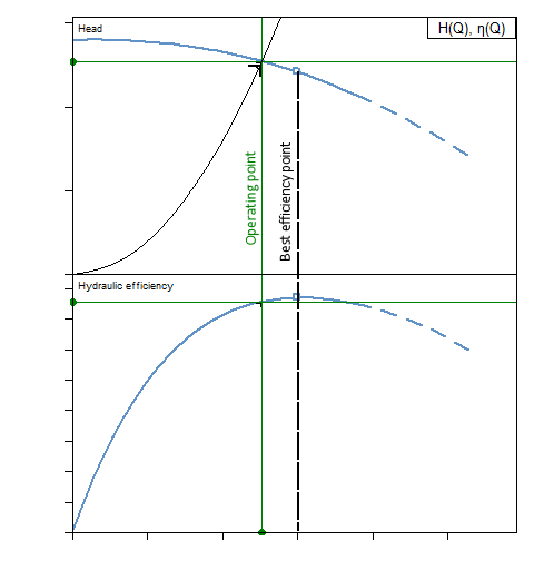
“It indicates the values of Flow and Head which will be obtained at stationary operation with the respective speed-related pump H-Q curve.”The specified duty point is defined to be that point on the system H-Q curve for which a pump is to be selected in line with the calculated hydraulic design criteria. The objective of the selection is (apart from other criteria, such as maximum efficiency) to minimise the deviation between the specified and the actual duty points.The actual duty point is always located at the intersection of pump H-Q curve and the actual system H-Q curve. At constant speed it moves up the pump H-Q curve with increasing friction losses towards a lower flow rate. The duty point should be chosen as close as possible to the point of optimum efficiency.
It is determined by the flow rate and head at the corresponding operating speed. When pumping highly viscous media, the pump characteristic curves and thus also the design point are shifted in relation to the characteristic curve recorded with water.
We use cookies to ensure that we give you the best experience on our website. If you continue to use this site we will assume that you are happy with it.ACCEPTDENYPrivacy policy

 pin, pout = pressures on suction respectively discharge liquid levels
ρ = fluid density
g = gravity (9.81 m/s2)
Hgeo = static height difference between suction and discharge liquid levels
Hl,tot = total pipe friction loss between inlet and outlet areas
vin, vout = mean flow velocities at inlet and outlet liquid level areasThe mean flow velocities at the inlet and outlet areas are, based on the Continuity Law, mostly insignificantly small and can be neglected, if the tank areas being relatively large compared to those of the pipe work. In this case, above formula will be simplified to:
pin, pout = pressures on suction respectively discharge liquid levels
ρ = fluid density
g = gravity (9.81 m/s2)
Hgeo = static height difference between suction and discharge liquid levels
Hl,tot = total pipe friction loss between inlet and outlet areas
vin, vout = mean flow velocities at inlet and outlet liquid level areasThe mean flow velocities at the inlet and outlet areas are, based on the Continuity Law, mostly insignificantly small and can be neglected, if the tank areas being relatively large compared to those of the pipe work. In this case, above formula will be simplified to: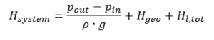 The static portion of the system H-Q curve, that part that is unrelated to the rate of flow, reads:
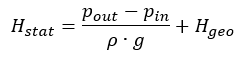 For closed circulating systems this value becomes zero.The total friction losses are the sum of the frictional losses of all components in the suction and delivery piping. They vary, at sufficiently large REYNOLDS numbers, as the square of the flow rate.
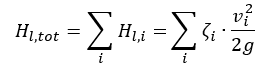
 g = gravity (9.81 m/s2)
Hl,tot = total friction loss between inlet and outlet areas
vi = mean flow velocities trough pipe cross-section area
Ai = characteristic pipe cross-sectional area
ζi = friction loss coefficient for pipes, fittings, etc.
Q = flow rate
k = proportionality factorUnder the above stated premises the parabolic system H-Q curve can now be drawn:
g = gravity (9.81 m/s2)
Hl,tot = total friction loss between inlet and outlet areas
vi = mean flow velocities trough pipe cross-section area
Ai = characteristic pipe cross-sectional area
ζi = friction loss coefficient for pipes, fittings, etc.
Q = flow rate
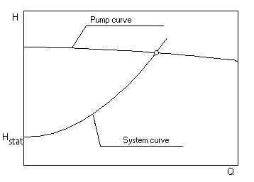
k = proportionality factorUnder the above stated premises the parabolic system H-Q curve can now be drawn: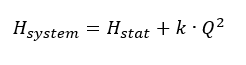 The proportionality factor k is determined of the specified duty point. The intersection of the system H-Q and the pump H-Q curves defines the actual operating point.