How a Diaphragm Pump Works
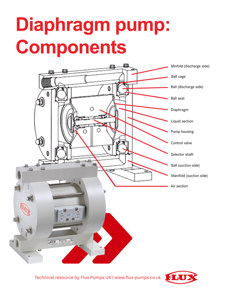
Image source: Gayleen Hodson, Flux Pumps Int. (UK) Ltd.
When air is directed into one side of the control unit, the diaphragm on that side is driven outward. At the same time, the shaft pulls the opposite diaphragm inward, creating suction and drawing liquid into the pump. The air flow then reverses, repeating the cycle and producing a continuous pumping action.
This design means double-diaphragm pumps can handle a wide range of fluids and applications safely and reliably:
- Self‑priming & dry‑run capable: Can start dry without pre‑priming and tolerate temporary dry running, however extended dry running should be avoided.
- Pneumatic operation: No electrical connection required. Flow rate can be adjusted simply by regulating air volume.
- Gentle fluid handling: The displacement principle is suitable for viscous, abrasive, shear‑sensitive, or solids‑laden media.
- Strong performance envelope: Depending on model, flow rates can exceed 1,000 l/min, with typical discharge pressure ratings up to 9 bar (special high pressure models are also available) and suction lift approaching 9 metres when primed.
- Self-stalling: When air inlet pressure matches liquid discharge pressure, the pump will stop. This feature can be useful when batch dispensing, however, the pump should never be left stalled for long periods without safety devices installed. A leak could result in significant damage to property or the environment.
- Certification & approvals: Explosion-proof (Ex) and food-safe models available.
For these reasons, diaphragm pumps are commonly found in industrial pumping applications, across almost every industry.
Above is the labelled component diagram referenced in this explanation, showing the main components involved in the pumping cycle - including the diaphragms, ball valves, manifolds, selector shaft, air section and liquid section.
Component Overview
- Manifolds (suction & discharge): Direct fluid into and out of the liquid side.
- Ball valves & seats: Control flow direction and prevent backflow during each stroke.
- Diaphragms: Flexible membranes that create suction and discharge through reciprocating movement.
- Liquid side: Houses the wetted components and manages product flow.
- Air side: Regulates compressed air supply and drives diaphragm motion.
- Control valve & selector shaft: Coordinate the alternating air feed to each diaphragm chamber.
- Pump housing: Provides structural support and maintains separation between air and liquid sections.
These components work together to deliver a controlled, repeatable pumping cycle. With considered pump selection and regular servicing, diaphragm pumps are proven to be a flexible, reliable solution for many industrial fluid handling projects.
Flux Pumps has been the global leader in drum pump technology for over 75 years. Flux quality, service life and reliability in even the toughest applications is recognised by our customers worldwide.
Find out more: